
Your first startup with a golden era Kswap can be an exciting nerve racking and aggravating experience all at once. Most of the time its aggravating due to unforeseen bs that prevents a clean start up. It can stem from be a simple thing like a misplaced or missing ground wire to a string of dumb asss things. Below is a compiled list of very common Kswap startup issues…
Wiring & ECU Based Issues
Ground wires
Kswaps are HELLA sensitive to grounds. If you don’t run the minimal amount you risk having startup issues and just overall weird ass electrical behavior. You MUST run at least 2-3 or more ground wires for the swap: two off the transmission to the left frame rail is mandatory, the engine harness to a valve cover stud (note: per Hondata’s advice and not on the intake manifold!), optional but a ground wire off the backside of a valve cover stud or right off the VTEC solenoid body to the right side shock tower. Up to you on the aesthetics, just get the got damn grounds on there!
Grounding main relay pin#2 – usually an EK civic based issue
So, this one seems to mostly revolve around the EK civic chassis, from what I’ve gathered. I’ve seen this happen with Rywire, Hybrid Racing, and Ktuned brand conversion harnesses. It has something to do with the wiring template these makers use. I don’t know who copied who but they all have the same issue where the symptom is that the vehicle will not get any power to the ECU thus affecting things like no fuel pump activity or no spark. The fix for this is by fishing out the EK’s main relay (located on the passenger side-of-dash area that faces against the door panel) and then adding/tapping a wire to the black main relay wire #2, and then mounting the other end of this wire directly to the chassis as shown. Again, aesthetics is up to you. Doing this can/will/should instantly bring power to the ECU.
[image]
JDM vs USDM ECU fuel pump relay pin differences
JDM and USDM K-series ECU’s use different pinouts for the fuel pump relay (FPR). This is because of the immobilizer system US ECU’s have and JDM 01-04 ECU’s lack – but I believe the 05-06 JDM RSX ECU’s actually have an immobilizer system yet are still wired as an 02-04 ECU. The E1 pin location is typically used for USDM/UK FPR and E10 is used for JDM ECU’s FPR. So, if you’re using a USDM engine harness (aftermarket or factory) with a JDM K-series ECU, your fuel pump isn’t going to activate. The fix is to simply move pin E1 down to E10 (just below E1).
TIP: If you never worry about FPR pinout wiring ever again, get a spare K-series ECU terminal pin w/about 1-2″ of wiring lead and pin it to the empty E10 slot, then splice/tap it over to E1. That way you’ll be proofed between USDM & JDM ECU’s!

Engine harnessing: Aftermarket good / aftermarket bad, budget K-swap tuck engine harness or straight-up wrong engine harness being used..
[lookin at you eBay/Amazon shiddy harnesses with big stupid ass yellow labels!]
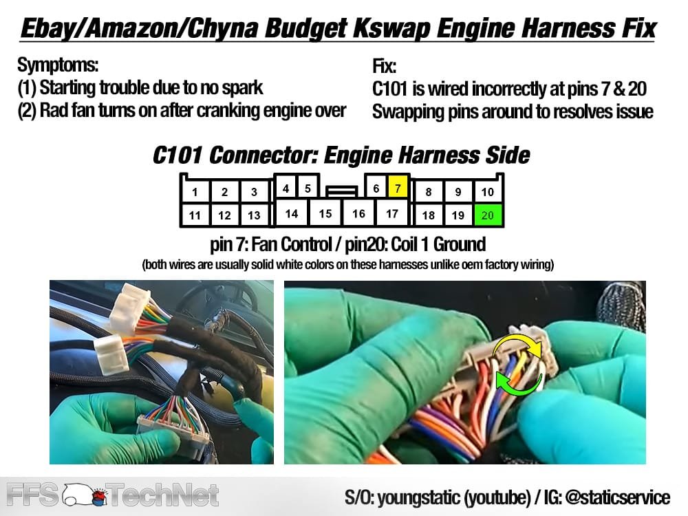
I’m not sure who originally figured this out, but I became aware of this fix through a post within the Facebook k20a.org / k-series tech groups that I usually frequent – a link was shared to Youtuber: YoungStatic whom shares knowledge regarding these budget ass Kswap tuck engine harnesses are incorrectly pinned at the C101 connector. Specifically pin 7 + pin 20 are cross-pinned. The symptoms of these crisscrossed pins are (1) no spark during the startup attempts and (2) and the radiator fan – if wired up and connected- turns on immediately with ignition on. The fix is to swap pin 7 and pin 20 around as shown below. PIN 7 is a radiator fan switch signal, PIN 20 is for #1 ignition coil pack ground. Stupidly, both of these wires are solid white color instead of matching oem factory wiring color scheme of solid green (Pin7) and black w/white strip (Pin20).
The other harness issue is using the wrong engine harness for your swap. Such as using an oem 05-06 RSX engine harness with an 02-04 ECU. These are incompatible with each other and this also ties over to the conversion harness as well making it an utter fluster cluck if you don’t do your K-swap wiring & ECU homework. The 05-06 RSX wiring and ECU are pinned differently than 02-04 RSX wiring and ECU, hence why they’re incompatible with each other. Places like HA Motorsports does sell ECU jumper harnesses though, that will down convert 05-06 ecu wiring for 02-04 ECU use, but your conversion harness must also pinned for 05-06 ECU wiring at the A+B connectors for this to fully work. It is possibly to stay 05-06 wiring & ECU but its not common practice for golden era Honda Kswaps…02-04 wiring & ecu is king – similar to how OBD1 ecu and wiring is king for B/D-series.
ECU K-PRO start up map/tune not setup properly
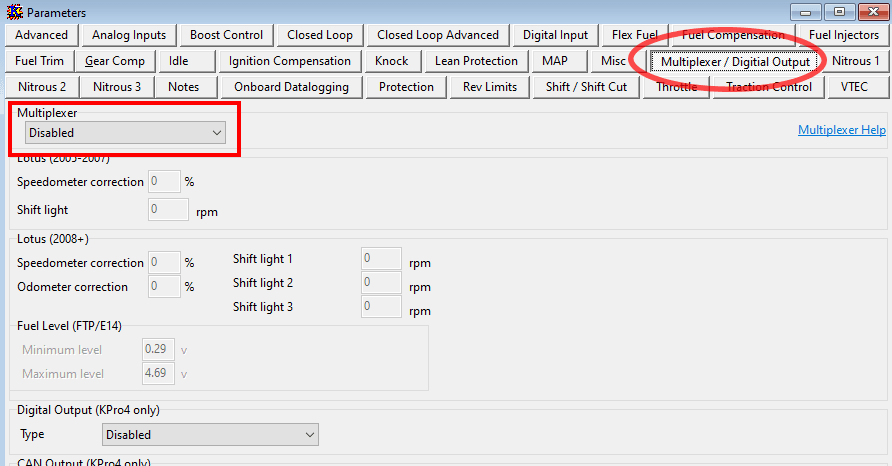
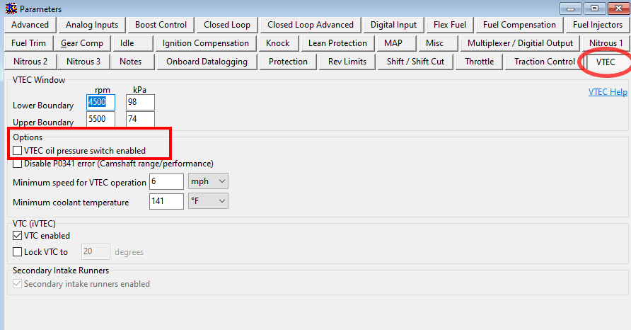
This one is pretty common too. A lot of people don’t know how to setup a startup tune or they do but get lost in what settings need to be disabled for golden era Kswap. It’s new territory for them and can seem daunting and are scared they might blow up their engine, which is understandable. But if they do make the attempt, they either pick the wrong map and continue with changing the wrong parameters. No matter what startup map is being used, these parameters should be disabled:
– Immobilizer system (directly affects fuel pump activity disable this mf immediately)
– Multiplexor system (for native K-series era car use only)
– Second 02 sensor
– Extra OBD2 functions (evap, purge system, ELD-optional – all unneeded)
– VTEC pressure switch (not used on JDM engines; does not hurt to have disabled at all)
– Knock sensor (not mandatory to disable, but disable if your knock sensor is broken or missing, will not hurt anything being disabled)
These are all functions that are useless for a golden era Kswap chassis.
-
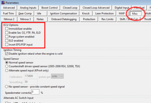
- Disable (uncheck box) Immobilizer & other unneeded OBD2 and emissions functions.

-
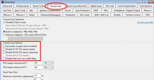
- Disable 2nd 02 and extra 02 functions (optional).

-

- Disable Multiplexor.
-
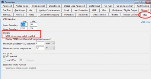
- Disable VTEC pressure switch.
Crisscrossed A+E ECU connectors
Of the three ECU connectors (A,B,and E) found on aftermarket engine and conversion harnesses, the “A” and “E” connectors CAN BE accidently crisscrossed! Thanks to the manufacturing laziness some of these harness makers, they don’t follow the unique factory OEM keyways for A and E connectors in preventing them from being idiot proof and crisscrossed. This is prevalent with tons of aftermarket brand tuck engine harnesses and conversion harnesses especially those trash-ass chyna budget tuck harnesses on Amazon/eBay/JackSpania/Bullboost/etc.. Symptoms of crossed A & E connectors is startup issues (fuel but no spark) and some other weird behavior. The A and B plugs always come off the engine harness and the E plug always comes off the of the conversion harness. If these makers would just fckin label the ECU connectors this wouldn’t be such a semi-wide spread problem! The other method is to double and cross-reference the wire colors for each connector pinout, but the easier method is already mentioned.
Sensor Based Issues
MAP & TPS sensors plugs are crisscrossed
This is a VERY common issue among the unknowing because of the same style connector both of these sensors have and are within the same vicinity of each other. This is especially a problem on unlabeled harnesses, like when using a factory OEM engine harness for a swap. When these plugs are crisscrossed in a golden era Kswap vehicle, there’s a 99% chance the MAP sensor will attain damage – internally blows out without any kind of obvious warning- upon vehicle startup (yes its THAT sensitive). I don’t think K-series era vehicles like the EP3 Civic and RSX have this problem. The rub here is that the ECU will NOT throw a CEL light for a bad MAP sensor! Wild right? So, the work around BEFORE VEHICLE STARTUP ATTEMPTS is to double check the MAP and TPS wire colors if you’re using an OEM engine harness for your swap and label them if you’re not sure which connector goes to either sensor. Obviously a kswap tuck harness have labeled sensors, so there’s no problem with those types of harnesses. The symptom of a blown map sensor is a hard startup – spins and hiccups like it wants to start with occasional backfire but will never turn over usually. One way to check (after the damage has been done) is if you’re using a Hondata KPRO ECU with your swap, open up the Hondata Kmanager software on your laptop, put Kmanager into LIVE/Datalog mode (F10 button), open the sensors list and look at the MAP sensor psi reading. If its showing -XXpsi its blown. It should be reading now lower than -XXpsi.
K20 vs K24 crank sensor differences
Everyone knows this by now right?? RIGHT?? K20 and K24 crank sensors differ in pinout wiring and connector key style. If you’re using a typical Kswap engine harness they are usually based of 02-04 RSX wiring, its 99.9% setup to use a K20 crank sensor and not a K24 crank sensor! If you try and use a K24 crank sensor with a Kswap harness pinned to use a K20 crank sensor YOU’RE GOING TO HAVE ISSUES. The only way you’ll get the K24 crank sensor to work is by swapping crank sensor wiring around and modifying the crank sensor connector to accept the K24 crank sensor. Hybrid Racing has a thorough article on this topic. Various symptoms can occur when improperly using a K24 crank sensor (all mentioned in the linked hybrid article).
Camshaft position sensors could be bad (one or both)
The two cam position sensors are located on the left side of the cylinder head. Either of these sensors could be bad or you’ve crisscrossed the harness connectors. They can go bad either at the same time or individually at some point in time. Factory Honda indicates the intake side is the “CMP” sensor and exhaust side is the “TDC” sensor. Normally, the ECU will throw a CEL if one or both of these sensors go bad. If only one is bad, you can actually swap them around to perform a trial & error test to confirm faultiness (CEL code will switch up). The actual sensors themselves are Hall-Effect type and are built the same. They work magnetically getting a reading from the cam pulse plates that are on the end of the camshafts. These sensor are not specific to which side of the head they’re used on, so that’s why you can swap them around and it will not hurt anything. Honda offers them in orientation styles – straight style or a 90 degree style. This doesn’t impact their performance, its just for plug orientation. Symptoms of a bad cam sensor(s) is difficult engine startup, can start up but runs terrible (stumbly) and can backfire, but should throw a CEL code!
Note: Rywire K-swap tuck engine harnesses have the CMP and TDC labeled reverse on purpose (TDC intake cam sensor / CMP exhaust cam sensor). He explains this on his K-swap engine harness product page. So if you run his harness and you’re having CMP and TDC cam position sensor codes its probably because you need to swap the connectors.
Mechanical Based Issues
K20Z1 throttle body MAP sensor situation
This one is unique. If for whatever reason you’re using a K20Z1 stock throttle body with your Kswap, and you decide to switch to any another intake manifold, other than the K20Z1 PRB intake manifold, you will have a problem with the MAP sensor getting a lack of vacuum source/feed (basically choking the MAP sensor). It’s because of how Honda slightly changed up the design of the K20Z1 throttle body’s backside compared to a K20A2 throttle body. There’s no slotted vacuum channel on the backside of a Z1 tb like there is a on a K20A2 tb. That slotted channel pulls vacuum from the throttle body mouth and feeds the MAP sensor. The wonky Z1 tb design has a small hole for the MAP so its super easy to choke it up! The result of a choked MAP sensor is stumbley startups or starts up fine but once you get on the throttle the engine falls on its face anything above 3000rpm. There’s two fixes for this as shown in the photos below. (1-best option) cut a slit from the MAP hole to the bore of the tb or (2) using an aftermarket Z1 thermal throttle body gasket, cut a channel open from the MAP hole to the bore hole of the gasket.
Cam & crank timing is off and/or crank pulse plate is installed wrong
Check your cam and crank timing and see if TDC is off. Being off timing can totally affect startup and overall running behavior. If timing is really off a CEL code will be thrown. Another thing to double check is the crank pulse plate. It’s marked ‘OUTSIDE’ on one side for a reason. So if you replaced any timing components and reassembled and forgot about this plates’ orientation you might need to go back and check! Symptoms of a inverted pulse plate is no start up, engine will just spin, and it will throw a CEL code for a crank related issue.
-

- White Mark = crank TDC.

-
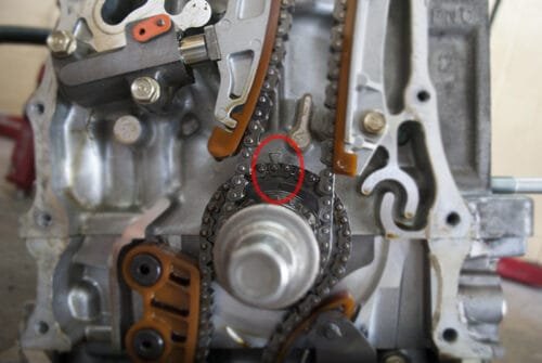
- Crank TDC markers on the inside w/timing cover removed.

-
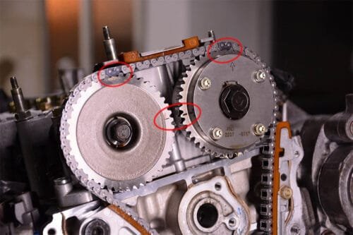
- Cam gear hash marks face to face at TDC. Chain alignment dots facing up. PS: don’t worry about the black chain links.

-
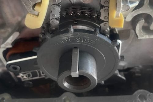
- Crank pulse plate in correct orientation.

Fuel system setup is wrong (regulator, pressure, and/or line setup)
If you have your fuel line setup incorrectly to the fuel pressure regulator, such as the fuel feed going to the return part of the regulator – this can impact startup. If your fuel pressure is too low and isn’t set somewhere in the 45-55psi range, can also impact startup and overall running conditions. A faulty regulator can also impact startup, so make sure you get a worthy brand regulator!
Blown Fuse (ELD!)
Check your fuses – engine bay and under dash fuse boxes! Especially the ELD fuse. When this one blows out just about everything goes dead.
No fuel in gas tank.
Dead battery.
Katman stole my children during the night